Here’s a short guide on how to restore your BW16 or rtlduino to the stock AT firmware for use with the ESP32 wardriver. You will need to get the AmebaD ImageTool from the SDK at https://github.com/ambiot/ambd_sdk as well as a copy of the original firmware. I don’t own the rights to distribute it, so you will have to find it yourself. Maybe look for it on a site that has an Archive of things from the Internet. In my case, the file was named “BW16 AT Firmware.bin” and the SHA256sum was c3d0df9fc7f67ffd62dd183ae61a4b8b0b2aa2e5eae1d936ebe5c565962fb259.
The first step for reflashing your rtlduino dev board is to install a couple of jumper wires between a few pins. You will need to connect TX_0 to LOG_TX and RX_0 to LOG_RX.
Once you have the wires connected, plug it into your computer with a USB cable, while holding the “Burn” button, press the “RST” button and let go of both to enter the bootloader.
Now in the AmebaD ImageTool, click Chip Select, choose “AmebaD(8721D)” and select your COM port. Browse for your file in the first Flash Download entry at address 0x08000000 and be sure to click the check box next to the image file. Click the download button and wait for the process to complete.
I have always loved electronics for as long as I can remember. As a young child, I remember building the example projects in my 75-in-1 electronics kit, carefully following the instructions to get a blinking light bulb or a simple AM radio receiver. It was my introduction to resistors, capacitors, switches, and relays. At the time, I didn’t know what I was doing, but it introduced me to what would become a lifelong hobby.
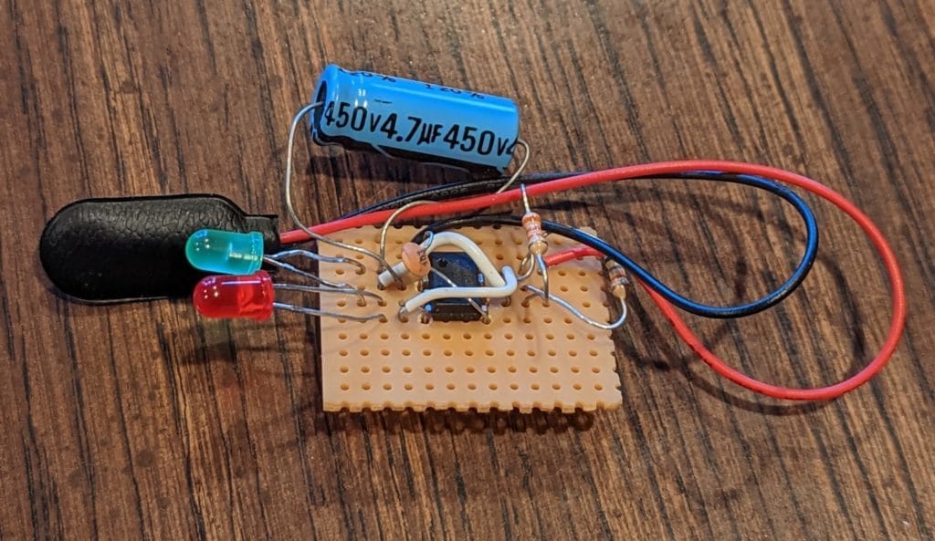
Fast forward to my freshman year of high school. By this time, I was very interested in computers, so I wanted to take the computer classes that were offered at school. One of the prerequisites happened to be an electronics class. It started off with basic housewiring, but then moved on to the electronics portion of the class. We learned about Ohm’s Law, seeing the interaction between voltage, resistance, and current and moved on to learning how to put our own circuits together. Enter the venerable NE555 timer IC. After practicing on a breadboard, we soon moved on to soldering our circuits on a piece of perfboard.
Actual NE555 project from high school configured as an astable multivibrator to blink 2 LEDs.
When deciding to get my first tattoo, I wanted something that was “just me.” During college, I was in and out of bands, thinking that I wanted to get something music related. I wanted to get a tattoo of a guitar with a face, screaming out music notes, but I never ended up getting it. A few months ago, over a decade later, I was asked by someone close to me if I would get a tattoo with them. I almost fell back on my original plan to get the guitar tattoo, but ultimately decided against it because music just isn’t as important to my life as it once was. The one thing that has always been a constant in my life was my love for electronics, so that’s what I decided to focus on.
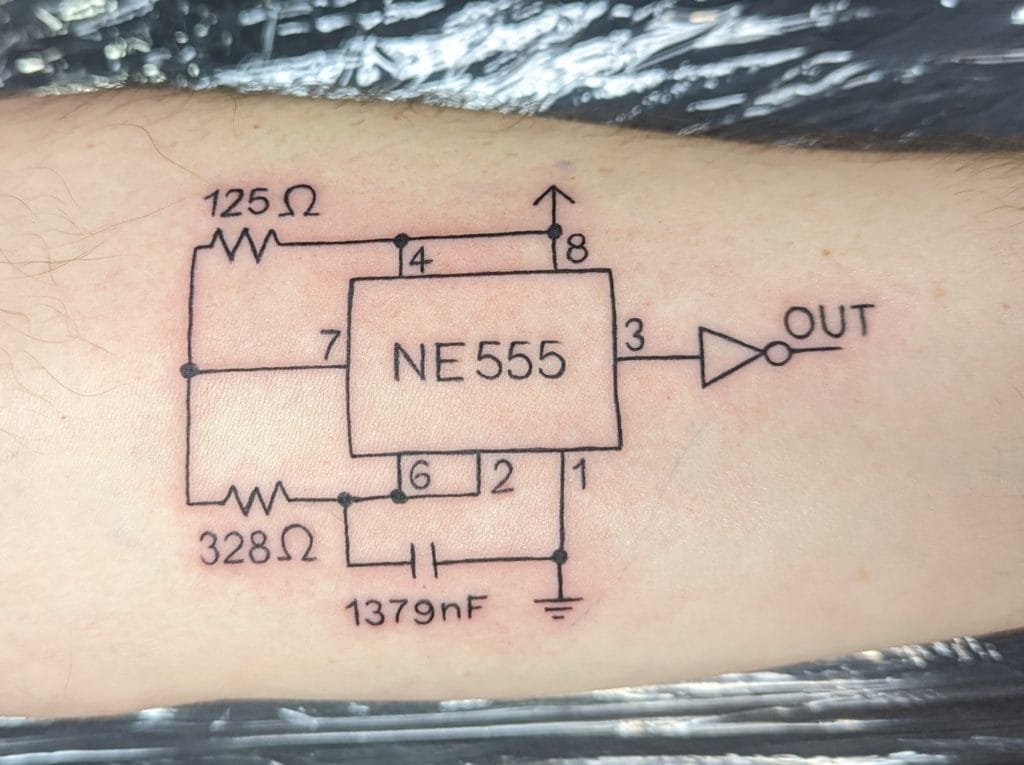
I started looking to the internet for some inspiration, seeing nonsensical “tribal” PCB traces and other simple circuits, but then it hit me. I should do a schematic for the 555. It wasn’t enough for me to just have a simple schematic, but I also wanted to hide some Easter eggs in it. The obvious first place to start was to set the frequency. 1337 Hz (aka elite) was an obvious frequency, but I also had the idea to hide another Easter egg in the duty cycle. Immature me originally had one idea, but I didn’t really want to tattoo that to myself forever, so I had to think of something else. Then it hit me: 42. The answer to life, the universe, and everything. But there was a problem with this value. Looking at the datasheet, you can configure the NE555 to have a duty cycle from 50-100%. The solution I came up with was to feed the output through an inverter, so now my target duty cycle was 58%.
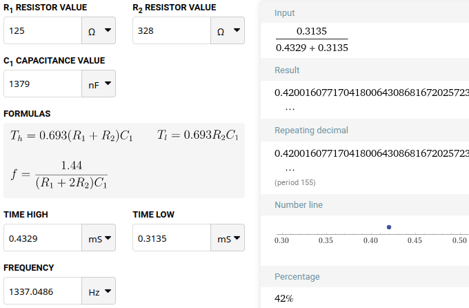
Now that I had my target outputs, it was time to calculate the values of R1, R2, and C. At this point, it was time to set my requirements. With the goal of this being a tattoo, I wanted everything to be whole numbers, as text tends to get fuzzier after a while. I also wanted to have my results be accurate to within 0.1 Hz and 0.1% for frequency and duty cycle respectively. After a little bit of calculation I settled on the values of R1=125 ohm, R2=328 ohm, and C=1379 nF. I sketched out the schematic, brought it to the tattoo parlor, and the rest is history.
Frequency set to 1337 Hz and inverted duty cycle set to 42%.
I also wanted to address a few common comments that I have seen in replies to my original Twitter post. First off, I am aware that I’m missing a few things from the schematic. There’s no decoupling capacitor, and no pin 5, nor a capacitor on said missing pin 5. If I were actually building this circuit, I absolutely would add them for more stable operation. I also didn’t specify a Vcc voltage. These are things that were not important to the meanings hidden in the calculations. This is a piece of art on my arm, with line art tattoos being more difficult to look good. There’s no hiding a mistake if something isn’t straight. I simply omitted the implied values to give the best chances for success. I also am aware that these are not common value components. Again, this is art with hidden meanings in it. I opted for the “oddly specific” to get my calculations to be nice and tidy. Even besides it being art, the analog world of electronics is messy and not everything comes out to be the exact value of a commonly available part. This is the reason why trimmer potentiometers and trimmer capacitors exist.